
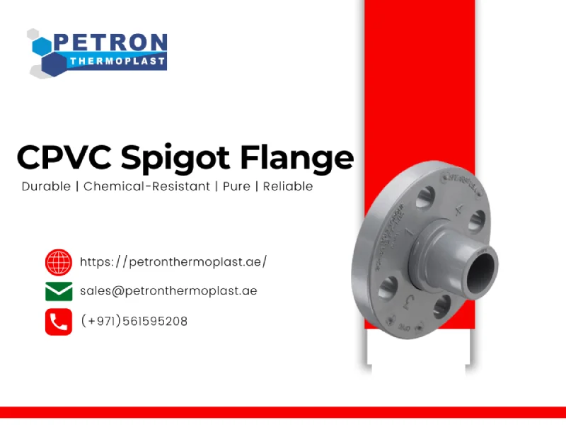
CPVC Spigot Flange
The CPVC Spigot Flange is a high-strength flange fitting used to connect CPVC pipelines to valves, pumps, or other equipment using a bolted flange connection. Featuring a spigot (plain end) on one side for solvent weld or fusion joining and a flat-faced flange on the other for secure bolted attachment, this fitting ensures a reliable and leak-proof interface in industrial piping systems. Manufactured from Chlorinated Polyvinyl Chloride (CPVC), it offers excellent resistance to heat, pressure, and corrosive chemicals, making it suitable for hot and cold water systems, chemical processing, and industrial fluid applications.
CPVC Spigot Flange
- Spigot End Connection: Allows easy solvent cement welding with CPVC pipes.
- Flange Interface: Provides strong, bolt-on connectivity to pumps, tanks, valves, and other flanged equipment.
- High Chemical Resistance: Withstands acids, alkalis, and corrosive industrial fluids.
- Thermal Stability: Suitable for high-temperature fluid handling up to 93°C (200°F).
- Strong & Durable: Designed for long-term performance under demanding conditions.
- Non-Corrosive & Non-Metallic: Ideal for use in environments prone to corrosion or chemical attack.
- Safe for Potable Water: Lead-free, non-toxic material certified for use in drinking water systems.
- Smooth Surface Finish: Minimizes flow resistance and internal wear.
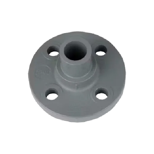
Technical Details of CPVC Spigot Flange
| Parameter | Specification |
|---|---|
| Material | CPVC (Chlorinated Polyvinyl Chloride) |
| Type | Spigot Flange – Spigot End × Flat Face Flange |
| Size Range | ½” to 6″ |
| Connection Type | Spigot (plain end for solvent weld) × Flange (drilled to standard bolt patterns) |
| Temperature Range | 0°C to 93°C |
| Pressure Rating | Up to 10 kg/cm² at 23°C |
| Color | Light Grey / Beige |
| Standards Compliance | ASTM D1784 / ASTM F439 / IS 15778 / ANSI B16.5 (Flange Drilling) |
| Applications | Industrial process piping, chemical transport, pump and valve connections |
| Installation Method | Solvent cement welding (spigot) and bolted flange connection |
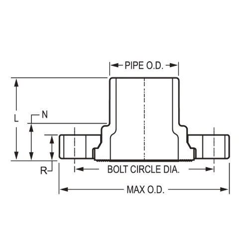
| Size | L | N | R | Bolt Circle Dia. | No. of Bolt Holes | Bolt Size | Min. Bolt Length | Max. O.D. | Approx. Wt. (Lbs. |
|---|---|---|---|---|---|---|---|---|---|
| 1/2 | 1-3/4 | 29/32 | 17/32 | 2-3/8 | 4 | 1/2 | 2 | 3-1/2 | 0.21 |
| 3/4 | 1-15/16 | 31/32 | 9/16 | 2-3/4 | 4 | 1/2 | 2 | 3-7/8 | 0.30 |
| 1 | 2-3/16 | 1-1/32 | 5/8 | 3-1/8 | 4 | 1/2 | 2-1/4 | 4-1/4 | 0.41 |
| 1-1/4 | 2-11/32 | 1-3/32 | 11/16 | 3-1/2 | 4 | 1/2 | 2-1/4 | 4-5/8 | 0.50 |
| 1-1/2 | 2-5/8 | 1-9/32 | 3/4 | 3-7/8 | 4 | 1/2 | 2-1/2 | 5 | 0.65 |
| 2 | 2-7/8 | 1-11/32 | 13/16 | 4-3/4 | 4 | 5/8 | 3 | 6 | 1.00 |
| 2-1/2 | 3-1/16 | 1-9/32 | 1 | 5-1/2 | 4 | 5/8 | 3-1/4 | 7 | 1.54 |
| 3 | 3-3/8 | 1-7/16 | 1-1/16 | 6 | 4 | 5/8 | 3-1/4 | 7-1/2 | 1.88 |
| 4 | 3-7/8 | 1-5/8 | 1-1/4 | 7-1/2 | 8 | 5/8 | 3-1/2 | 9 | 3.12 |
| 6 | 4-3/4 | 1-25/32 | 1-9/32 | 9-1/2 | 8 | 3/4 | 4 | 11 | 4.79 |
| 8 | 5-7/8 | 1-15/16 | 1-3/8 | 11-3/4 | 8 | 3/4 | 4-1/2 | 13-1/2 | 8.17 |
| 10 | 8 | 2-1/4 | 1-5/8 | 14-1/4 | 12 | 7/8 | 5 | 16 | 16.09 |
| 12 | 8-1/2 | 2-3/16 | 1-5/8 | 17 | 12 | 7/8 | 5 | 19 | 22.70 |
-
L – Overall Length / Thickness of Flange
-
N – Bolt Hole Diameter
-
R – Raised Face Diameter (or Bolt Circle Radius)
-
Bolt Circle Dia. – Diameter of Bolt Circle (centerline through bolt holes)
-
No. of Bolt Holes – Total number of bolt holes in the flange
-
Bolt Size – Nominal diameter of the bolts used
-
Min. Bolt Length – Minimum required bolt length for assembly
-
Max. O.D. – Maximum Outside Diameter of flange
-
Approx. Wt. (Lbs.) CPVC – Approximate weight of the flange in pounds for CPVC material

Customization & Processing Options
Customizations Option Available for CPVC Spigot Flange
At Petron Thermoplast, we offer customized PVDF fittings to meet your specific system requirements.
Customization options include:
- Tailor-made dimensions and wall thicknesses
- Custom-molded and machined PVDF fittings
- Pre-fabricated manifolds and assemblies
- Choice of connection type (butt fusion, socket fusion, or flanged)
- OEM branding or marking options