

PVDF Flanged Diaphragm Valve
The PVDF Flanged Diaphragm Valve is a corrosion-resistant flow control solution engineered for highly aggressive and demanding fluid applications. Constructed from premium Polyvinylidene Fluoride (PVDF), this valve is ideal for use in chemical processing, pharmaceuticals, and ultra-pure water systems. Its flanged end design allows for easy integration into standard piping systems, while the diaphragm mechanism provides precise throttling and shut-off capabilities without direct contact between the actuator and the process fluid.
PVDF Flanged Diaphragm Valve
- High Chemical Resistance: PVDF body resists acids, bases, and solvents, suitable for aggressive media.
- Flanged Connection: Ensures easy installation, alignment, and removal in standard piping systems.
- Diaphragm Isolation: Prevents fluid contamination by isolating the working parts from the media.
- Leak-Proof Performance: Provides bubble-tight sealing for both on/off and throttling functions.
- Low Maintenance Design: Simplified internal components reduce wear and servicing needs.
- Corrosion-Proof Hardware: Ideal for outdoor and corrosive environments.
- Precise Flow Control: Excellent for regulating flow in critical process applications.

Technical Details of PVDF Flanged Diaphragm Valve
| Technical Parameter | Specification |
|---|---|
| Body Material | PVDF (Polyvinylidene Fluoride) |
| Diaphragm Material | EPDM, PTFE/EPDM laminated, or FKM |
| Valve Type | Diaphragm Valve – Flanged Ends |
| Connection Type | Flanged (DIN, ANSI, JIS standards available) |
| Size Range | 1/2″ to 6″ (15 mm to 150 mm) |
| Pressure Rating | Up to 6 bar (varies with size and diaphragm) |
| Temperature Range | -10°C to +120°C (depending on diaphragm type) |
| Operation | Manual handwheel, pneumatic, or electric actuated |
| Flow Characteristic | Linear to slightly modified equal percentage |
| Mounting Position | Any position |
| Standards Compliance | ISO, DIN, ANSI (model specific) |
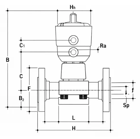
| d | DN | PN | B | B1 | C | C1 | F | H | H1 | f | U | Ra | Sp |
|---|---|---|---|---|---|---|---|---|---|---|---|---|---|
| 20 | 15 | 10 | 148 | 25 | 66 | 24 | 65 | 130 | 97 | 14 | 4 | 1/4'' | 13.5 |
| 25 | 20 | 10 | 151 | 30 | 69 | 24 | 75 | 150 | 97 | 14 | 4 | 1/4'' | 13.5 |
| 32 | 25 | 10 | 159 | 33 | 78 | 24 | 85 | 160 | 97 | 14 | 4 | 1/4'' | 13.5 |
| 40 | 32 | 10 | 163 | 30 | 82 | 24 | 100 | 180 | 97 | 18 | 4 | 1/4'' | 14 |
| 50 | 40 | 10 | 207 | 35 | 112 | 24 | 110 | 200 | 126 | 18 | 4 | 1/4'' | 16 |
| 63 | 50 | 10 | 245 | 46 | 142 | 24 | 125 | 230 | 157 | 18 | 4 | 1/4'' | 16 |
| 75 | 65 | 10 | 245 | 46 | 142 | 24 | 145 | 290 | 157 | 18 | 4 | 1/4'' | 21 |
d – Nominal Bore / Tube Outside Diameter
DN – Nominal Diameter (Diameter Nominal, in mm)
PN – Nominal Pressure Rating (Pressure Nominal)
B – Overall Height of Valve (Bottom to Top)
B1 – Bottom Clearance / Lower Body Height
C – Center to End Dimension
C1 – Center to Top Body Dimension
F – Flange Thickness / Face-to-Face Flange Length
H – Face-to-Face Length / Overall Length
H1 – Actuator Height (Top Section Height)
f – Flange Bolt Hole Diameter
U – Number of Bolt Holes
Ra – Surface Roughness (Ra Value, usually in µm)
Sp – Spigot Diameter / Spacing Dimension

Customization & Processing Options
Customizations Option Available for PVDF Flanged Diaphragm Valve
At Petron Thermoplast, we offer customized PVDF fittings to meet your specific system requirements.
Customization options include:
- Tailor-made dimensions and wall thicknesses
- Custom-molded and machined PVDF fittings
- Pre-fabricated manifolds and assemblies
- Choice of connection type (butt fusion, socket fusion, or flanged)
- OEM branding or marking options